Radian
Radian, a Premier flight control system designed for seamless flight performance and full Pixhawk ecosystem compatibility.


General
- The Radian is a premier flight control system designed for seamless compatibility with ArduPilot, PX4 and betaflight.
- Radian is engineered for superior performance and versatility using redundant high quality sensors.
- It is the perfect solution for a broad spectrum of UAV applications, from recreational drones to complex commercial and industrial operations
Main Features
-
MCU:
- STM32H743
- ARM Cortex-M7 @ 480 MHz
- 2 MB Flash, 1 MB SRAM
-
IMUs:
- TDK ICM42688P – high-performance, low-noise 6-axis motion sensor
- Bosch BMI270 – low-power, high-precision 6-axis IMU
-
Barometers:
- Bosch BMP280 (soon upgrading to BMP390) – high-resolution pressure sensor
- ST LPS22HBTR (soon upgrading to DPS368) – ultra-compact digital output barometer
-
Compasses:
- Bosch BMM150 – low-power 3-axis geomagnetic sensor
- ST LIS3MDL – high-performance 3-axis magnetometer
-
Power Input:
- Dual redundant power inputs
- Integrated dual eFuse for enhanced protection
- Built-in voltage sensing for battery monitoring
- Onboard DC-DC conversion for stable regulated power delivery
Resources
Firmware
- The Radian flight controller currently supports the following firmware types:
- Ardupilot
- PX4
- Betaflight
- INAV
- Currently the hardware definitions are being merged to the public repositories of each codebase.
- Until then, the various versions will be flashed before the units are shipped.
- In case you need the firmware files please contact us.
Mechanical
-
The radian flight controller consists of 2 components:
- FCU - a detachable flight controller unit.
- Carrier Board - a carrier board for the FCU expanding connectors and power capabilities.
-
Weight
- FCU: 5 [g]
- Carrier Board: 9 [g]
- Total Weight: 14 [g]
-
Dimensions
- Board dimensions are defined in millimeters.
- Mounting hole size is M4, suitable for M3 stacking with silicone dampers.
- Carrier board: 46 × 38 mm (M4 mounting holes, 30.5 × 30.5 mm spacing).
- Radian core module: 32 × 32 mm (M2 mounting holes with integrated standoffs).

Electrical
General
- For each connector specification, the pinout orientation is determined by an arrow pointing to pin 1.
Specifications
-
Input voltage: 8-50.4 [V] (3S-12S)
-
GPIO / Communication logic level: 3.3 [V]
- Warning: do not operate at any other logic voltage level.
-
Top View

-
Bottom View

Electrical pinout
- Connector orientation
- JST-GH cables shall be oriented according to the illustration

- JST-GH cables shall be oriented according to the illustration
FRC Button
![]()
- To enter DFU mode, use the FRC button according to the following steps:
- Power off the board
- hold the FRC button
- Power up the board
- release the FRC button
- The Radian is now in DFU mode
POWER1

-
Connector Definition
Type Part Number Part Name Board Connector SM06B-GHS-TB JST-GH Cable Connector GHR-06V-S JST-GH -
Connector Pinout
Pin Name 1 Battery 2 Battery 3 Current sense (logic 3.3v) 4 Voltage sense (logic 3.3v) 5 GND 6 GND
POWER2
-
Connector Definition
Type Part Number Part Name Board Connector SM06B-GHS-TB JST-GH Cable Connector GHR-06V-S JST-GH -
Connector Pinout
Pin Name 1 Battery 2 Battery 3 Current sense (logic 3.3v) 4 Voltage sense (logic 3.3v) 5 GND 6 GND
PWR1 VSense - Solder Jumper

PWR2 VSense - Solder Jumper

TELEM1
-
Connector Definition
Type Part Number Part Name Board Connector SM06B-GHS-TB JST-GH Cable Connector GHR-06V-S JST-GH -
Connector Pinout
Pin Name 1 5V Power Output 2 UART_TXD (logic 3.3v) 3 UART_RXD (logic 3.3v) 4 NC 5 NC 6 GND
TELEM2
-
Connector Definition
Type Part Number Part Name Board Connector SM06B-GHS-TB JST-GH Cable Connector GHR-06V-S JST-GH -
Connector Pinout
Pin Name 1 5V Power Output 2 UART_TXD (logic 3.3v) 3 UART_RXD (logic 3.3v) 4 NC 5 NC 6 GND
GPS

-
Connector Definition
Type Part Number Part Name Board Connector SM10B-GHS-TBT JST-GH Cable Connector GHR-10V-S JST-GH -
Connector Pinout
Pin Name 1 5V Power Output 2 UART_TXD (logic 3.3v) 3 UART_RXD (logic 3.3v) 4 I2C_SCL (logic 3.3v) 5 I2C_SDA (logic 3.3v) 6 SAFETY_SW 7 SAFETY_SW_LED 8 3.3V_OUT (logic 3.3v) 9 BUZZER (logic 3.3v) 10 GND
SERVO (PWM)
-
Connector Definition
Type Part Number Part Name Board Connector SM10B-GHS-TBT JST-GH Cable Connector GHR-10V-S JST-GH -
Connector Pinout
Pin Name 1 SERVO1 2 SERVO2 3 SERVO3 4 SERVO4 5 SERVO5 6 SERVO6 7 SERVO7 8 SERVO8 9 GND 10 GND
CAN

-
Connector Definition
Type Part Number Part Name Board Connector SM04B-GHS-TB JST-GH Cable Connector GHR-04V-S JST-GH -
Connector Pinout
Pin Name 1 5V Power Output 2 CAN_H (logic 3.3v) 3 CAN_L (logic 3.3v) 4 GND
USB
-
Connector Definition
Type Part Number Part Name Board Connector SM04B-GHS-TB JST-GH Cable Connector GHR-04V-S JST-GH -
Connector Pinout
Pin Name 1 5V Power Input 2 USB_D- 3 USB_D+ 4 GND
I2C
-
Connector Definition
Type Part Number Part Name Board Connector SM04B-GHS-TB JST-GH Cable Connector GHR-04V-S JST-GH -
Connector Pinout
Pin Name 1 5V Power Output 2 I2C_SCL 3 I2C_SDA 4 GND
RC

-
Connector Definition
Type Part Number Part Name Board Connector SM03B-GHS-TB JST-GH Cable Connector GHR-03V-S JST-GH -
Connector Pinout
Pin Name 1 5V Power Output 2 PPM_IN 3 GND
Troubleshooting
Compass calibration
ArduPilot
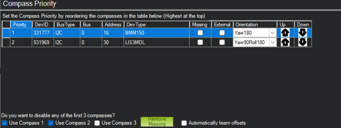
- Under certain conditions, using COMPASS_AUTO_ROT=2 fails to calibrate due to incorrect orientation.
- To solve this use COMPASS_AUTO_ROT=0, set the compass parameters manually like the image below and re-calibrate.
- Make sure to complete accelerometer and gyro calibration before calibrating the compass.
- If after calibration one of your compass offsets exceeds 600, it is likely indicating there is magnetic interference. Check for sources of interference and try calibrating again.